The tweeter speaker protection circuit
#ALPHA Lab #speakerprotectioncircuit #audiocircuitDC speaker protection circuit explained Part I | ALPHA LabHi friend!In this video, I analyze the working pr.
Speaker protection circuit
Speaker Protection Circuit (Stereo) This is the speaker protection circuit, provides stereo speaker protection and prevents switch-on clicks and DC components on the output of the amplifier connected. Speaker Protection Components List: R1,R2 : 3K3 R3,R4,R5,R6,R7 : 8K2 R8,R9,R10,R11 : 330K R12,R13 : 18K
12+ Speaker Protection Circuit Diagram Robhosking Diagram
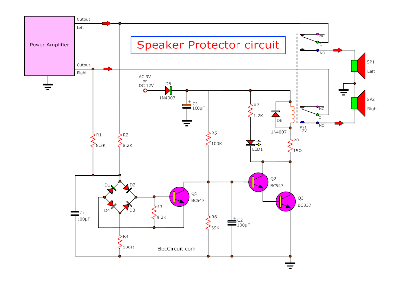
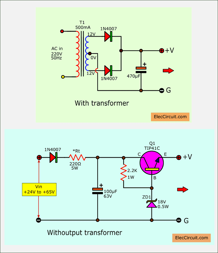
How Speaker protection circuit Works Simple speaker protection circuit 1. Soft start 2. DC voltage protection Power supply source Building and test circuit How to use Speaker Protector circuit with adjustable sensitive 4 qualities that a good circuit should have Download This Simple Delay Speakers Related Posts
Speaker protection circuit
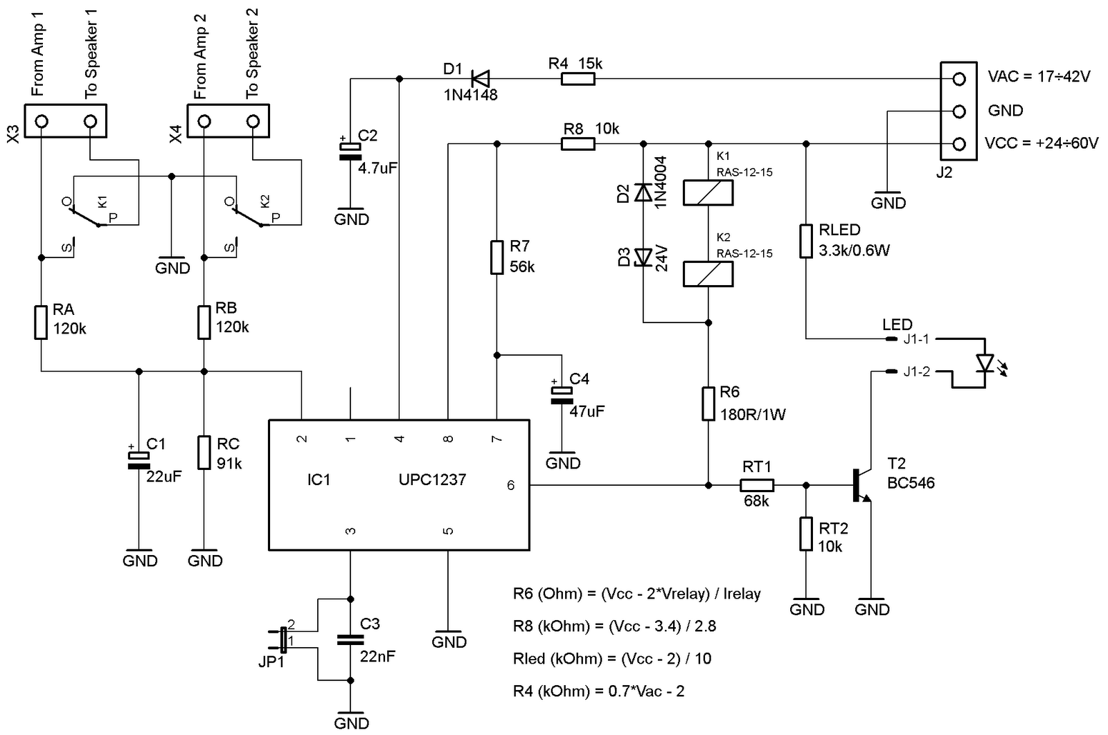
Simple Speaker Protection Circuit for Power Amplifiers with Balanced Outputs XEN Audio October 2013 Introduction If one search on the internet, one would find tons of speaker protection circuits for single-ended power amplifiers. There are also simple-to-use ICs designed for the purpose, like uPC1237 or TA7317, but

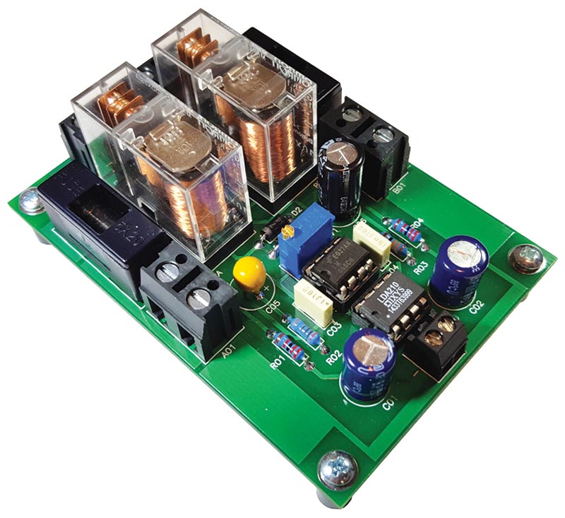
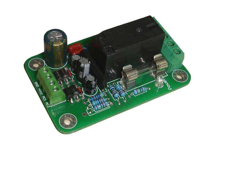
Speaker protection circuit kit
A speaker protection and muting circuit is installed between a DC coupled audio power amplifier output and the speaker. Its main purpose is to disconnect the speakers as soon as a large DC voltage that can damage the speaker is present at the output of the amplifier. This can happen when the amplifier is malfunctioning.

5.1 Amplifier Speaker Protection Circuit TechSaw
I bought the speaker protection from a local DIY electronic store see the 50 watts ocl power amp here https://youtu.be/0c6KAWGQtZQbut the circuit detect only.
How to Protect Loudspeakers from Over Current Surge
uPC1237 is a well known IC used for protecting the speakers form DC as well as amplifiers from over current. Almost any Sony amplifier starting from the lower range and right up to the higher-end ES series are using this chip. So I thought was a good idea to make a stand alone module which could be used by the DIY community.

DIYfan Speaker protection with uPC1237
Feb 7, 2020. #3. A protection circuit monitors the output offset voltage, and will usually disconnect the speakers if the offset voltage exceeds about 1 volt. In addition they usually monitor output transistor currents and will 'trip' if the current exceeds a safe value.

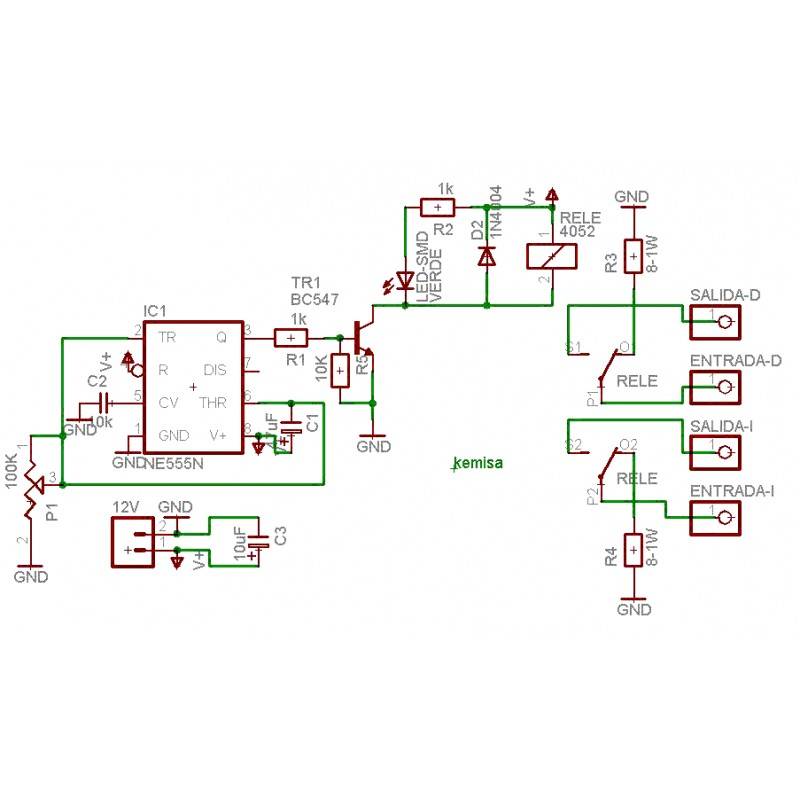
Speaker protector circuit diagram using NE555N Electronics Help Care
About Press Copyright Contact us Creators Advertise Developers Terms Privacy Policy & Safety How YouTube works Test new features NFL Sunday Ticket Press Copyright.
Speaker Protection and Muting with an Optical Coupler Nuts & Volts Magazine
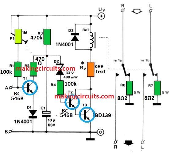
Circuit operation is simple and straightforward. To understand how it works, let's divide the circuit to 4 sections: Visual Indicator Time Delay and Relay Driver Speaker Switch DC Detector How each of these sections works is briefly described below:
Speaker Protection Circuit (Connexelectronic) Hifime Audio
with the characteristics of the speaker protection circuit; detects a DC voltage leakage which can damage speakers, the speaker disconnects the amplifier from short-circuit (overcurrent protection), overheating protection and thermostat with LED indicator present. Speaker Protection Circuit
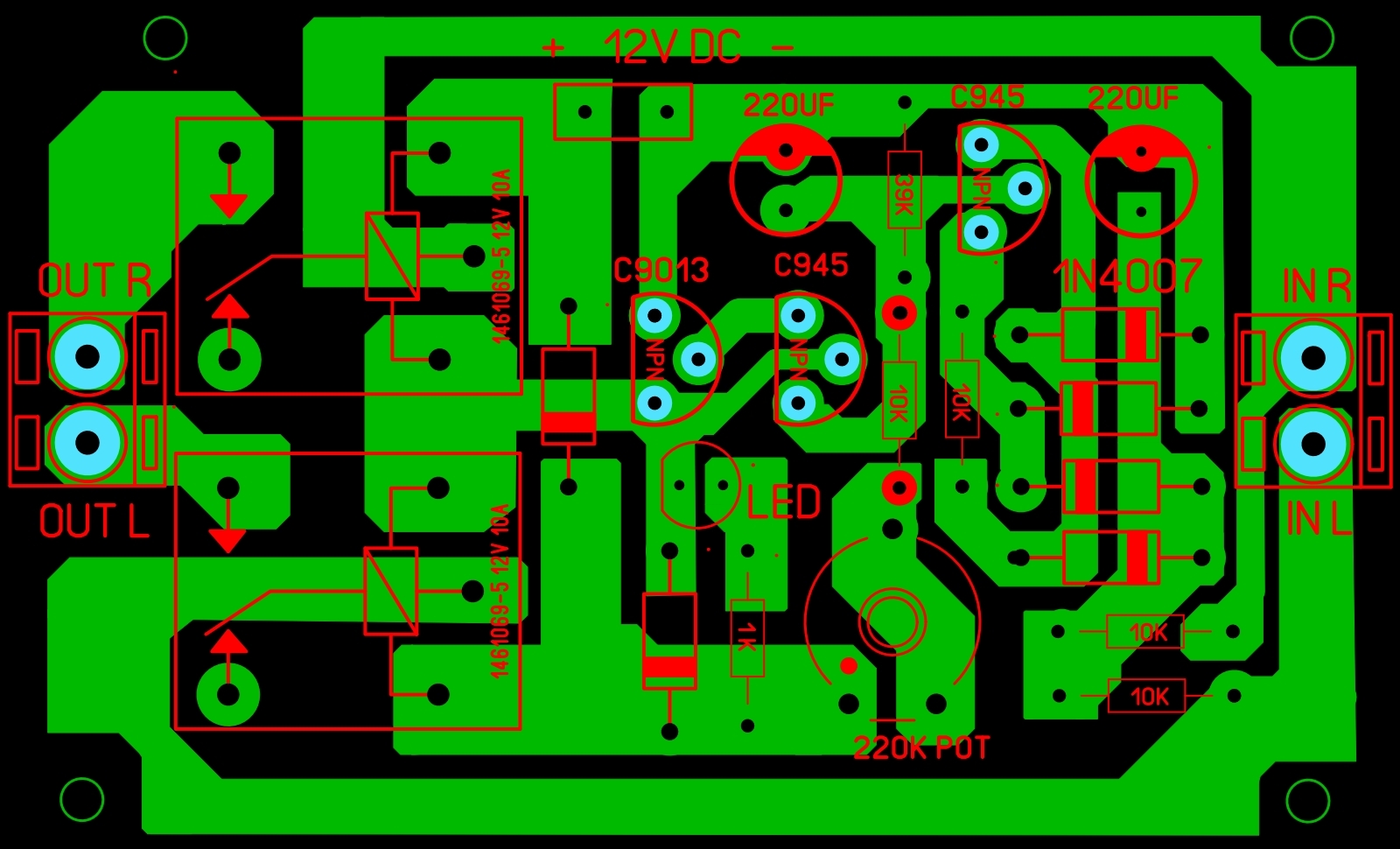
Speaker Protection Board Circuit Diagram Soldering Mind
The speaker protection circuit detects the DC voltage at the amplifier output and disconnects the speaker. The DC voltage detection level of the protection circuit is very low (0.7…1V) so that the speaker is protected from being exposed to high voltage.
How to make Speaker Protector Circuit with DC Protection Speaker protector diagram YouTube
My requirements for a speaker protection circuit: 1. Delayed connection of speaker after power on. 2. Instant speaker disconnection on power off. 3. Quick speaker disconnect in case of DC on amplifier output. 4. Latch relays off when any fault occurred. 5. Can be used for my dual mono design without hard wiring ground of the two amps together.
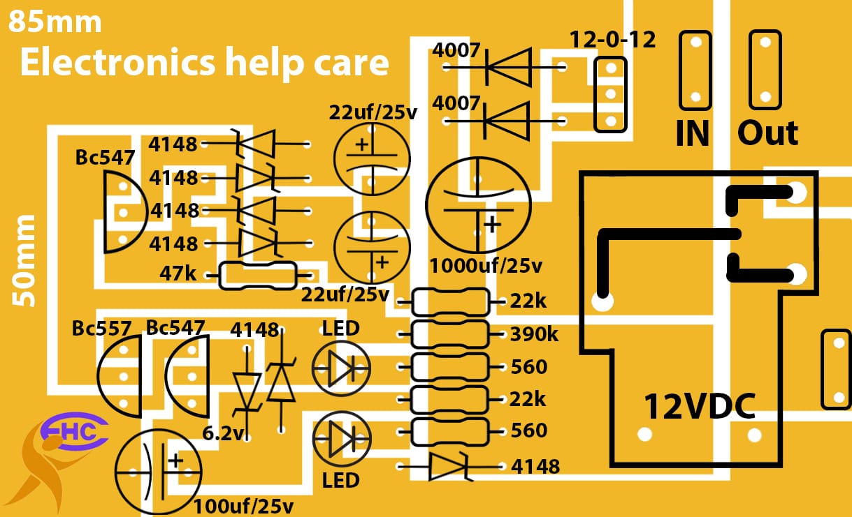
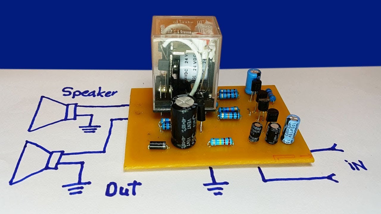
Speaker protection circuit diagram Electronics Help Care
1. E50 Speaker Strobe models have in-out wiring terminals that accept two #12 to #18 American Wire Gauge (AWG) wires at each screw terminal. Strip leads 3/8 inches and connect to screw terminals. 2. Break all in-out wire runs on supervised circuits to assure integrity of circuit supervision as shown in Figure 2. The
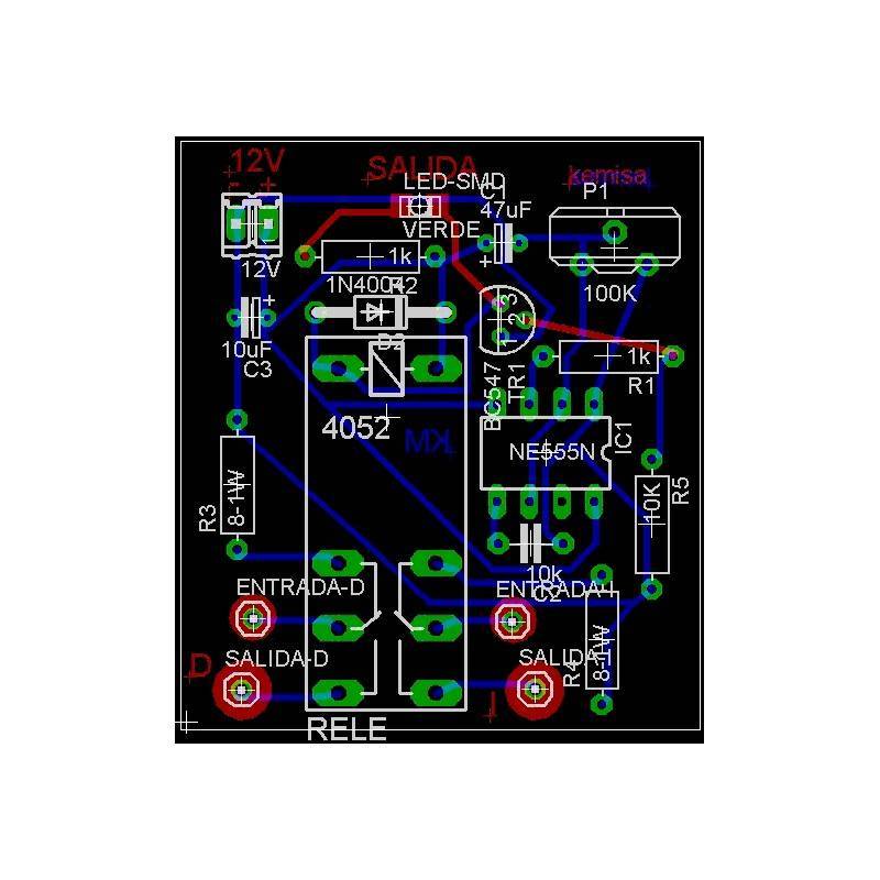
DIY Speaker Protection uPC1237 with speaker terminal schematic and Komitart LAY6.
How to make Speaker Protector Circuit with DC Protection - Speaker protector diagramThank You for watching my video! please kindly assist me to like share an.
DIYfan Speaker protection with uPC1237
This is the speaker protection circuit, provides stereo speaker protection and prevents switch-on clicks and DC components on the output of the amplifier connected. Speaker Protection Components List: R1,R2 : 3K3 R3,R4,R5,R6,R7 : 8K2 R8,R9,R10,R11 : 330K R12,R13 : 18K R14,R15,R16,R17 : 47K R18 : 47